Delivering Reliability in Additive Manufacturing with Quality Control
In 2019, Domin became the first company in the world to sell an off-the-shelf product manufactured using metal Additive Manufacturing. Being the first meant having to solve problems and create quality control measures without accepted solutions.
One of the core challenges with adopting any new production process is the quality control required to achieve consistency for product reliability. The most likely failure for our products is material fatigue under repetitive loading.
The fundamental question is: how do we ensure metal Additive Manufacturing achieves near zero operating fatigue failures?
In order to answer this, it was necessary to go back to first principles and construct a closed loop process which met the highest standards of reliability with the minimum overall cost. This article sets out the thinking behind the choices made and outlines the adopted processes for quality control.
Establishing Realistic Targets for Reliability and Quality Control
Any Quality Control System has the aim of maximising the benefits whilst minimising costs. We operate within a wide range of sectors including industrial, robotics, mobile hydraulics, automotive and aerospace. When setting our quality standards, we need to be mindful of many requirements.
For example, Aerospace tends to specify failure rate as a probability of failure (e.g. 1 x 10⁻⁹ /hr), and Industrial in terms of number of rejects (e.g. 6σ). If a product life of 10,000 hours is assumed, one would expect one failure in 10,000 opportunities for an “Extremely Remote” failure (1 x 10⁻⁸ /hr). This equates to approximately 4σ (1 in 16,000).
Therefore, we set the target of Structural Failure Rate – 4σ over the product life
Cost of Quality Control – <5% of total production cost, including:
- Cost of conducting quality monitor intervention
- Cost of valid defect – rejected material and rework
- Cost of ‘false positive’ – rejected material which would have been acceptable to customer
- Cost of ‘false negative’ – ’Escapes’, delivered hardware which results in customer failures
Framing the Problems
Faced in general, mechanical failures occur where the loads induced during operation exceed the component’s material capabilities, as shown in the graph below. The frequency they occur depends on the variation of use and the variables of production. We are interested in both the basic margin of safety represented by the difference in mean values, as well as the distribution scatter. Both influence the region of overlap where failures occur.
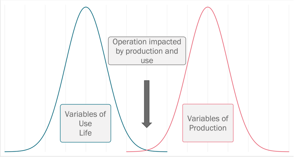
Essentially, a reliable product is one where the variables of production and variables of use do not impact on satisfactory operation.
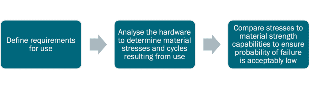
Metallic structures frequently fail through a combination of load and repetitive cycles, generally referred to as fatigue. Our aim is to ensure sufficient margin and controlled scatter to ensure a low probability of failure. The engineering approach to fatigue follows a well-established path which has three basic steps:
Looking at these steps in more detail, with respect to loading requirements, there are universally accepted standards for fluid power specifying the rating and use of equipment. These are embodied within ISO standards for industrial equipment, SAE ARP for aircraft and MIL and DEF standards for the military. For analysis we can also rely on proven techniques for calculating stresses in mechanically loaded components, in particular high resolution Finite Element Analysis (FEA) techniques.
The challenge for metal Additive Manufacturing lies in determining the threshold stress which will result in a failure. Classically, material fatigue properties have been determined by the testing of machined coupons of the material of interest. These were subject to varying dynamic loads to determine the cycles to failure. This generated a curve which could then be factored for additional variables (from experience and test) to obtain a ‘safe life’ curve where the probability of failure was acceptably low.
These ‘factors of safety’ for metallic fatigue of wrought or cast components have been determined over the best part of a century of testing and supported by years of refinements within the production processes. Not only does industry understand scatter but has also been able to steadily improve the consistency of materials through processes such as Vacuum Arc Remelting (VAR).
Understanding Metal Additive Manufacturing Fatigue
In 2012, we realised the potential for metal Additive Manufacturing to revolutionise an industry that currently relied upon 20th-century technology. With this vision we drew upon our understanding, from many years of aerospace equipment design, of the need for reliable material property data, so embarked on a programme of material fatigue testing.
To date (2021), we have tested to failure (or >1 x 10⁶ cycles) over 700 samples, mostly with maraging steel, using Laser Powder Bed Fusion (LPBF) process. The aim has been to establish fatigue strength and scatter about the mean. Although this work is ongoing, we have established a better understanding of process variables.
These include machine manufacturers, machine-to-machine variability, machine variability over time, powder type, sample build angle, metal Additive Manufacturing layer thickness, material section, HIP treatment, notch sensitivity, fatigue R ratio, etc. This graph shows a number of typical S-N curves.
In summary, the data supported the following conclusions (to date):
- At best, the LBPF metal Additive Manufacturing process is capable of producing samples with the fatigue strength close to wrought material values in the ‘as built’ condition
- Consistency of properties within a build batch was in line with the best-wrought material
- Fatigue strength can be maintained in thin-walled samples
- Care is required in assessing stresses in thin-walled samples given discrepancies between “CAD modelled” and “metal Additive Manufacturing build” dimensions, which vary with machine manufacturers
- Large variations exist between the properties achieved by metal Additive Manufacturing machine manufacturers using the same metal powder
- There are significant variations in properties achieved by identical machine types using the same powder managed by different organisations in different locations
- Generally, metal Additive Manufacturing machine manufacturers have an incomplete understanding on the fatigue property performance of the current offering of machines
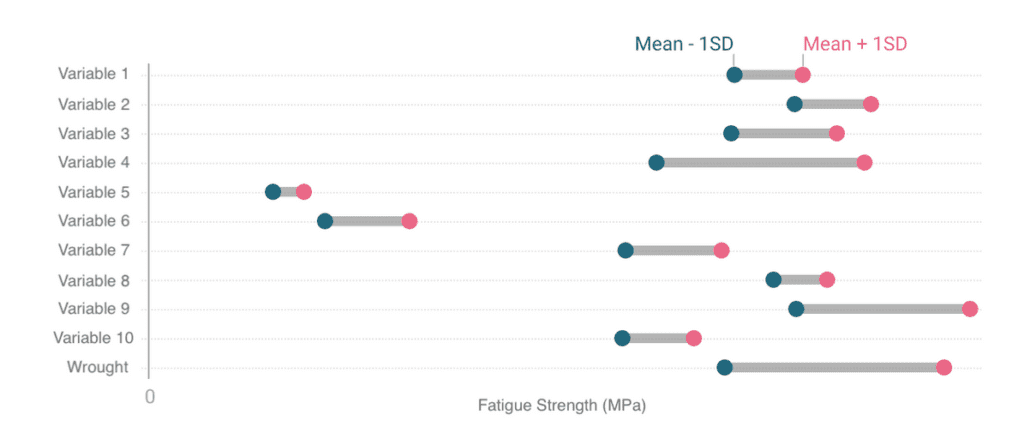
- The overall variation in fatigue strength obtained for the same material between ‘best’ and ‘worst’ was approximately 500%
Domin experienced a wide variation of fatigue strength achieved for the same material, in the same heat treatment condition, with nominally similar tensile strength.
The most positive aspect of the data was the stability in strength from a given machine in a given location with operating parameters and powder type fixed. In order to implement an appropriate production control system, we reviewed the requirements and quality control mechanisms from first principals.
Formulating the Right Solution
The starting point was to review the classical methods for fatigue failure management, namely Process Control and Design Margin. The aim being that the process control can achieve a sufficiently small scatter in fatigue properties such that one does not require excessive design margin and hence wasted component size and mass.
Initial fatigue testing looked promising. Whilst there was a large variation in fatigue strength with build orientation and notch condition (in the “as built” state), scatter within a build, and between builds on an individual machine appeared good (typically with a Coefficient of Variation of 9% or less). As we expanded testing to include nominally identical machines tested in different locations and over a period of time, a more complex set of data resulted.
After much consultation with machine suppliers, the uncomfortable conclusion was reached that there were significant process variations which were affecting fatigue strength that were not fully understood.
In formulating a solution, we had to add these “unknown factors” with the already large list of Fatigue Strength Influencing parameters shown below. Two components are of interest to each of these variations. Firstly, the overall average effect on fatigue strength, and secondly the variation from mean in production.
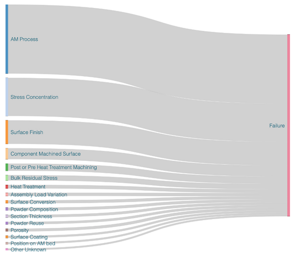
Unknown influencers are particularly relevant with respect to our overall objective of elimination of fatigue failures, they invalidate any quality control process which do not directly measure component fatigue strength. Any proxy measurement of fatigue strength (such as tensile testing) would need to add margin for unknown influencers which may affect fatigue strength, but not necessarily the proxy test.
The classical approach relies on the prediction of events with low probability based on an extrapolation of data around the mean. Events are assumed to be statistically random and follow a near Gaussian distribution. Skewed data erodes the effectiveness of this model.
It was clear from the test results that a degree of process monitoring would need to be incorporated in order to achieve our objectives. Considerations included: visual inspection, tensile testing, hardness testing, computed tomography, melt pool monitoring batch fatigue testing and product fatigue testing. The assessment of process took the form of a matrix incorporating the process variable and the quality method.
Each combination was assigned a capability based on an ability to accurately recognise faults. Additionally, each Quality Control measure was assessed with respect to cost and are described in the following image.
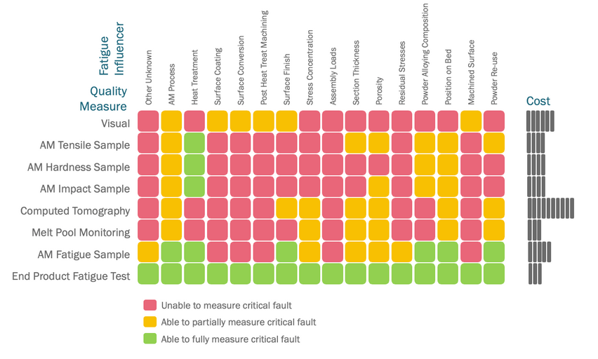
In the case of Computed Tomography, trials were conducted to check suitability. A clear picture emerges, highlighting the limitations of many Quality Control Measures in their ability to identify fatigue strength variations in metal Additive Manufacturing builds.
There is not a clear correlation between physical features or tensile properties and the resultant fatigue strength.
Ultimately, the best test for fatigue properties is a cyclic loading test to failure. This provides a definitive answer whether the overall metal Additive Manufacturing process is in control, but is still one step removed from our overall aim of reliable operation of the product in production. Fortunately, steel exhibits an Endurance Limit where the continued cycling at stresses below this limit is highly unlikely to result in failure. It’s possible to test to this limit without damaging or limiting the life of the product.
Once it was established that fatigue testing of each sample of the product was the most effective way of achieving the overall objective, we set about ensuring an efficient means of implementation.
Establishing a Quality Control Process
Much of the Quality Control Processes we adopted are familiar and follow generally adopted best practice. This applies to the operation and maintenance of metal Additive Manufacturing machines and material handling. The design and development testing also follows industry standards for design margin.
The key difference is in the continual monitoring of fatigue strength performance of the metal Additive Manufacturing process. This is achieved through two feedback mechanisms. Firstly, the embedding of fatigue coupon samples within each build, and secondly the 100% testing to an endurance limit of each valve before delivery.
The objective is to use the data to minimise variations so that the amount of end testing can gradually be reduced, without compromising product reliability.
Summary of Domin Process

- Define Coefficient of Variance: coupon fatigue test evaluating all major variables to confirm appropriate Coefficient of Variance
- Design analysis: design analysis to achieve fatigue test pass, and production reliability targets, based on ‘infinite life’ at system pressure
- Type Test: Production Type Test to relevant Aerospace or ISO standards
- Process Fatigue Monitoring: use of coupon fatigue samples in each build, tested to destruction to confirm margin and scatter (number reduced as process confirmed ‘in control’)
- Product Testing: test each deliverable unit at 1.05 x Rated Pressure for 1×10⁶ Cycles
- Feedback: appropriate corrective action to design or process to maintain margins
Is It Time to Revolutionise Your Hydraulics?
As illustrated above, we have thoroughly evaluated the Additive Manufacturing process for the purpose of creating high-quality, reliable and efficient hydraulic valves and systems.
So, why not put us to the test? Simply contact us or use the chat on this page and explore how we can help. We can supply test valves, discuss your precise requirements and work on delivering the perfect solution to fit your needs.